2018年8月13日 星期一

用SensorBoard 玩Arduino (2) 硬體的介紹

2 硬體的介紹
 () Arduino介紹
1.腳位介紹


(1)一般介紹
控制器
 ATmega328
 運作電壓
 5V
 輸入電壓 (建議)
7 -12V
 輸入電壓 (限制)
 6-20V
 數位 I/O Pins 
 14腳位 (D0~D13)
 3, 5, 6, 9, 10  11 共六支腳 提供PWM輸出
 類比輸入 Pins
 6腳位 (A0~A5)
 I/O Pin直流電流 
4 0 mA
 3.3V Pin直流電流 
 50 mA
 Flash 記憶體
 32 KB (ATmega328) 其中 0.5 KB  用於 bootloader
 EEPROM
 1 KB (ATmega328)

(2) 數位 I/O Pins (0~13)
共計14 支數位 I/O Pins,可以當作 input output 使用。利用 pinMode(), digitalWrite(), digitalRead() 等函式存取。其中幾支腳有特殊的功能:
 串列通訊
 0(RX)  1 (TX) 用來接收(RX)與傳輸(TX) TTL訊號的序列資料。這 兩支腳也連接到ATmega8U2USB串列晶片
 外部中斷
 2  3 這兩支腳可以利用低電壓觸發外部中斷,請參考attachInterrupt()
 PWM
 (前置~符號) 3, 5, 6, 9, 10,11六支腳。透過 analogWrite()函式可提供8-bit PWM 輸出
 SPI
 10(SS), 11(MOSI), 12(MISO), 13(SCK)這四支腳搭配 SPI Library 可提供SPI 序列通訊
 LED
 13。內建一顆 LED連接該Pin,當 pin腳為HIGH 時,LED亮,當pin腳為 LOW時,LED關閉

(3)電源:可使用USB或外部電源。

 VIN 
當使用外部電源時,輸入電壓給Arduino版,可透過這個Pin腳提供電壓
 5V 
該腳輸出5V的穩定電源,該板可提供(7-12V)直流電源,USB接口(5V)
 3.3V 
產生3.3伏的電源板上穩壓器。最大電流消耗為50mA
 GND 
接地引腳
 IOREF
提供Arduino板的參考電壓


()Sensor Board基本介紹(Arduino UNO擴充板)
簡介
S4A/S2A Sensor Board for Arduino v2主要設計給Arduino/Motoduino S4A/S2A初學者使用的一塊互動板,結合麥克風、按鍵開關、光源感測、滑桿式可變電阻、RGB LED 、蜂鳴器等元件,以及四組RJ11的接頭可供外部連接其他裝置或元件,如接溫濕度感測器、土壤濕度感測器等。另外預留一個藍芽孔位給需要無線傳輸的使用者。可利用此無線傳輸跟Android手機或電腦溝通


1技術規格
接腳
功能
D2/D3
RJ11外接其他裝置
D2
無段式按鍵開關
D5
彩色RGB LED - 綠色
D6
彩色RGB LED - 紅色
D9
彩色RGB LED - 藍色
D9
蜂鳴器(RGB LED 的藍色互相切換使用)
D10
LED 綠色
D11
LED 紅色
D12
LED 黃色
D12/D13
RJ11接頭外接其他裝置
A0
滑桿可變電阻(10K) 有效行程30mm
A1
光感測元件
A2
麥克風
A3/A4
RJ11接頭外接其他裝置
A4/A5
RJ11接頭外接其他裝置
D0/D1
藍芽孔位(UART)

用SensorBoard 玩Arduino (1) 環境的安裝與設定

Scratch 2.0(離線版)+ Transformer + Arduino IDE +motoblockly_broker的安裝
總共要裝下以程式(校內檔案下載   需登入google)

裝完之後在桌上會有以下捷徑

Transformer是台灣宇宙機器人 kodorobot 團隊寫的轉譯程式,可以將Scratch 2.0 的指令轉譯成Arduino的程式執行,寫作介面為Scaratch2.0。安裝次序為 Adobe AIR Scratch Offline EditorArduino IDE Transformer感謝台灣宇宙機器人 kodorobot 團隊提供學校教育單位免費使用。
(一)   Scratch Offline Editor( Scrathc 離線版)
(二)   Adobe AIR
軟體下載:

(三)   Arduino IDE 安裝Motoduino_v11函式庫的安裝)
先把Motoduino_v11.zip解壓縮Motoduino_v11後,再把的資料夾裝到C:\Users\user\Documents\Arduino\libraries\


(四)   Transformer 2.0安裝


Transformer的程式一定得在Arduino板連接電腦的狀況下才能執行,可利用慧手科技自行開發的圖控式程式寫作軟體motoBlockly(網址為 www.motoblockly.com )先產生Arduino Sketch的程式碼,再利用Arduino IDE將程式碼上傳至Arduino中,如此日後Arduino板只需接上電源便可達到脫機運行的效果了。

五、Moto Blockly線上編程式網站與motoblockly_broker_setup.exe的安裝
()Moto Blockly網站http://www.motoblockly.com/
(利用積木來寫程式,且可以很方便的將積木程式轉換成Arduino語言)


二、motoblockly_broker:直接燒錄程式 不用透過Arduino IDE

2018年6月2日 星期六

107.06.02卓越組期末報告初選結果


一、入選名單如下:


二、期未報告注意事項:
1.比賽時間:107.06.09(六) 08:20~11:50(比賽時間09:00~11:00) 於三樓大會議室
2.每組報告時間:4分30秒為限(4分舉牌,4分30秒按鈴結束)
3.評分標準:表達(50%)、專題(50%)
4.獎勵方式
(1)特優:共取3組,每組獎金500元,並獲得下學期晨讀演示。
(2)優點:共取3組,每組獎金300元
(3)優點:共取5組,每組獎金200元,

三、關於今天報告建議如下:
(一)報告技巧

  1. 報告音量太小了,聲音太小易顯示自信不足。
  2. 報告時,應準備好檔案在隨身碟中,以節省時間。
  3. 報告時應面對觀臮時間多一些,而不是一直看著ppt檔
  4. 掌握各組報告的特點與精華,吸引大家。
  5. 專有名詞,宜作簡易說明,以減少觀眾認知落差。

(二)ppt檔

  1. ppt檔文字太多了,關鍵字部份請加以標示。
  2. 圖片比文字更有說服力。
  3. ppt檔少用淺色系文字,效果較差,且字型應該統一


ps.今天報告影片檔因攝影機受電腦病毒影響,目前搶救中…@@....

如果0609拿到獎品的人 可以到http://2013cloud.blogspot.com/search/label/wemos
看相關文件。

2018年5月2日 星期三

卓越組107.05.05期末報告

一、報告組別與緗序


二、網路硬碟資料

三、報告部份
上傳網址:
  1. 請加入個人的心得與想法,並請於5/27以前完成第一次ppt的上傳。
  2. 於6/2進行報告,11組取5組,擇優1-2組。
  3. 報告時每組6分鐘,評分標準 
  4. (1)內容40%  (2)ppt呈現 20%  (3)台風與問題回答 30% (4)同學互評 10%


四、上傳後的資料的網址:
請點選這裏

2017年9月19日 星期二

用webmos d1 mini 玩物聯網(3)-用電腦控制wemos上的LED燈

一、教學目標:
1開啟 wemos的伺服器模式
2.透過瀏覽器來控制 wemos的led燈

二、接線圖
led燈正極接在D5,負極接GND

三、程式碼


/*
    This sketch demonstrates how to set up a simple HTTP-like server.
    The server will set a GPIO pin depending on the request
      http://server_ip/gpio/0 will set the GPIO2 low,
      http://server_ip/gpio/1 will set the GPIO2 high
    server_ip is the IP address of the ESP8266 module, will be
    printed to Serial when the module is connected.
*/

#include <ESP8266WiFi.h>

#ifndef STASSID
#define STASSID "your-ssid"
#define STAPSK  "your-password"
#endif

const char* ssid = STASSID;
const char* password = STAPSK;

// Create an instance of the server
// specify the port to listen on as an argument
WiFiServer server(80);

void setup() {
  Serial.begin(115200);

  // prepare LED
  pinMode(LED_BUILTIN, OUTPUT);
  digitalWrite(LED_BUILTIN, 0);

  // Connect to WiFi network
  Serial.println();
  Serial.println();
  Serial.print(F("Connecting to "));
  Serial.println(ssid);

  WiFi.mode(WIFI_STA);
  WiFi.begin(ssid, password);

  while (WiFi.status() != WL_CONNECTED) {
    delay(500);
    Serial.print(F("."));
  }
  Serial.println();
  Serial.println(F("WiFi connected"));

  // Start the server
  server.begin();
  Serial.println(F("Server started"));

  // Print the IP address
  Serial.println(WiFi.localIP());
}

void loop() {
  // Check if a client has connected
  WiFiClient client = server.available();
  if (!client) {
    return;
  }
  Serial.println(F("new client"));

  client.setTimeout(5000); // default is 1000

  // Read the first line of the request
  String req = client.readStringUntil('\r');
  Serial.println(F("request: "));
  Serial.println(req);

  // Match the request
  int val;
  if (req.indexOf(F("/gpio/0")) != -1) {
    val = 0;
  } else if (req.indexOf(F("/gpio/1")) != -1) {
    val = 1;
  } else {
    Serial.println(F("invalid request"));
    val = digitalRead(LED_BUILTIN);
  }

  // Set LED according to the request
  digitalWrite(LED_BUILTIN, val);

  // read/ignore the rest of the request
  // do not client.flush(): it is for output only, see below
  while (client.available()) {
    // byte by byte is not very efficient
    client.read();
  }

  // Send the response to the client
  // it is OK for multiple small client.print/write,
  // because nagle algorithm will group them into one single packet
  client.print(F("HTTP/1.1 200 OK\r\nContent-Type: text/html\r\n\r\n<!DOCTYPE HTML>\r\n<html>\r\nGPIO is now "));
  client.print((val) ? F("high") : F("low"));
  client.print(F("<br><br>Click <a href='http://"));
  client.print(WiFi.localIP());
  client.print(F("/gpio/1'>here</a> to switch LED GPIO on, or <a href='http://"));
  client.print(WiFi.localIP());
  client.print(F("/gpio/0'>here</a> to switch LED GPIO off.</html>"));

  // The client will actually be *flushed* then disconnected
  // when the function returns and 'client' object is destroyed (out-of-scope)
  // flush = ensure written data are received by the other side
  Serial.println(F("Disconnecting from client"));
}
2.並修改如下

const char* ssid = "xxxx";////WeMos要連上的基地台 ssid
const char* password = "xxxxxx";  //基地台密碼

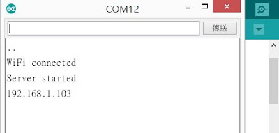
3.點選序列埠螢幕(serial monitor)可以看到以下畫面 server已經啟動,且ip為192.168.1.103(每一台分到ip是不一樣的。


4.打開瀏覽器,網址部份打入:
http://192.168.1.103/LED=ON,出現如下的畫面,燈變


http://192.168.1.103/gpio/LED=OFF ,出現如下的畫面,燈變


用webmos d1 mini 玩物聯網(2)-簡易的blink程式

一、教學目標:
1.認識WeMos D1 mini 的腳位,並修改內建程式blink程式
2.利用範例程式進行wifi scan

webmos d1 mini


腳位圖

D4:內建LED燈
D1,D2 I2C通訊協定。


腳位圖

二、程式碼

//WeMos內建的led燈的腳位為 gpio2 或是D4
//pinMode 可寫成 pinMode(2,out)
//或是 pinMode(D4,out)

void setup() {
  // initialize digital pin LED_BUILTIN as an output.
  pinMode(D4, OUTPUT);
}

// the loop function runs over and over again forever
void loop() {
  digitalWrite(D4, HIGH);   // turn the LED on (HIGH is the voltage level)
  delay(1000);                       // wait for a second
  digitalWrite(D4, LOW);    // turn the LED off by making the voltage LOW
  delay(1000);                       // wait for a second
}